Squeeze the end of a garden hose and the water speeds up. Everyday experience with fluids says that a narrowing passage accelerates a flow and a widening one slows it down. A rocket nozzle appears to ignore this. It narrows to a throat, where the gas of the model engine is moving at about \(1.2\ \mathrm{km/s}\) , and then it flares out into a bell several times wider than the chamber, and in that widening bell the gas more than doubles its speed.
The bell is not decoration. Chapter 4 showed that the exit velocity depends on how far the pressure falls, and stated an exit pressure without saying how a nozzle produces it. Chapter 3 used, twice, the claim that the mass flow through an engine does not care what the pressure is outside. Both rest on one fact about gases, namely that a gas moving faster than sound responds to a change of area in the opposite way to a gas moving slower than sound. This chapter derives that fact, and from it the size of the throat, the Mach number and pressure at any area, the thrust coefficient promised in Section 3.7, and the limit on how large a nozzle can be made before the flow refuses to follow it.
5.1 Sound, and the number that compares a flow with it
A small disturbance in a gas, a slight local squeeze, does not stay put. It travels, and the speed at which it travels is a property of the gas. To find that speed, consider a weak pressure pulse moving along a tube of constant cross-section \(A\) through gas at rest.
Assumptions. System: a thin control volume that moves with the pulse and encloses it. In that frame the flow is steady: undisturbed gas with pressure \(p\) and density \(\rho\) enters the front at the unknown wave speed \(c_s\) , and leaves the back with pressure \(p+\mathrm dp\) , density \(\rho+\mathrm d\rho\) , and speed \(c_s-\mathrm du\) . The changes are infinitesimal. Friction and heat conduction are neglected.
Mass. What enters leaves: \(\rho\,c_s\,A=(\rho+\mathrm d\rho)(c_s-\mathrm du)A\) . To first order, \(c_s\,\mathrm d\rho=\rho\,\mathrm du\) .
Momentum. By Theorem 3.1 the net force on the contents, \(pA-(p+\mathrm dp)A\) , equals the momentum flux out minus the momentum flux in, \(\rho c_sA\,[(c_s-\mathrm du)-c_s]\) . So \(\mathrm dp=\rho\,c_s\,\mathrm du\) .
Eliminating \(\mathrm du\) between the two gives \(\mathrm dp=c_s^2\,\mathrm d\rho\) . The wave speed is fixed by how much the pressure rises when the gas is compressed. Which compression? The pulse passes too quickly for heat to flow and it is too weak for friction to matter, so the gas is compressed adiabatically and reversibly, at constant entropy. Section 4.7 already computed the derivative of pressure with respect to density along an isentrope.
Proposition 5.1 (speed of sound). Small disturbances travel through a gas at the speed \(c_s\) given by \(c_s^2=(\partial p/\partial\rho)_s\) . For an ideal gas,
The speed of sound depends on temperature and on the gas, and on nothing else. It is the root-mean-square molecular speed \(\sqrt{3RT}\) of Example 4.2 multiplied by \(\sqrt{\gamma/3}\) , about \(0.63\) for \(\gamma=1.2\) , which makes sense: a pressure disturbance is carried by molecules bumping into their neighbours, so it cannot travel faster than the molecules themselves do. For air at \(288\ \mathrm K\) the formula gives \(\sqrt{(1.4)(287.0)(288)}=340\ \mathrm{m/s}\) , the familiar value.
Definition 5.1 (Mach number). The Mach number of a flow at a given point is the ratio of the flow speed to the local speed of sound, \(M=u/c_s\) . A flow is subsonic where \(M<1\) , sonic where \(M=1\) , and supersonic where \(M>1\) .
The physical meaning of the dividing line is about messages. Every change in a flow is announced to the rest of the gas by pressure disturbances, which travel at \(c_s\) relative to the gas. In a subsonic flow a disturbance can make headway upstream, so the gas ahead can adjust to what is coming. In a supersonic flow the gas carries every disturbance downstream faster than it can travel upstream. Nothing that happens downstream can be felt upstream.
Example 5.1: Sound speeds along the model engine
Chamber. With \(\gamma=1.2\) , \(R=361.5\ \mathrm{J/(kg\cdot K)}\) , and \(T_c=3600\ \mathrm K\) ,
Sound travels almost four times faster in the chamber than in room air, because the gas is hotter and lighter.
Exit of Example 4.5. There \(T_e=1535\ \mathrm K\) and \(v_e=2993\ \mathrm{m/s}\) , so
What to notice. Between chamber and exit the flow speed rose from nearly zero to \(2993\ \mathrm{m/s}\) while the sound speed fell from \(1250\) to \(816\ \mathrm{m/s}\) , because the gas cooled. The Mach number grows for both reasons. Somewhere in between the two speeds were equal, and the rest of the chapter turns on where.
A convenient formula follows at once. From the energy equation of Section 4.3, \(c_pT_c=c_pT+\tfrac12u^2\) . Divide by \(c_pT\) and substitute \(u^2=M^2\gamma RT\) and \(c_p=\gamma R/(\gamma-1)\) :
With the isentropic relations of Proposition 4.4, the Mach number at a point then fixes every property there as a fraction of its chamber value:
5.2 What a change of area does
Now let the gas flow steadily along a passage whose cross-sectional area \(A\) changes gradually from station to station.
Assumptions. Quasi-one-dimensional flow: at each station the pressure, density, temperature, and speed \(u\) are uniform across the passage, and the velocity is along the axis. The flow is steady, adiabatic, and frictionless, hence isentropic, and the gas is calorically perfect. The wall slope is small enough that the sideways component of velocity carries negligible momentum and energy.
The assumptions are good in the core of a smoothly shaped nozzle. They fail near the wall, where friction acts in a thin layer; near the throat, where the wall curves sharply; and wherever the gas near the wall leaves at an angle, which Section 5.7 treats as a correction.
Take as control volume the slice of passage between two neighbouring stations, where the area changes from \(A\) to \(A+\mathrm dA\) and the flow properties change by \(\mathrm dp\) , \(\mathrm d\rho\) , \(\mathrm du\) .
Mass. The mass flow \(\dot m=\rho\,u\,A\) is the same at every station. Taking the logarithm and differentiating,
Momentum. Three pressure forces act on the gas in the slice along the axis: \(pA\) forward on its upstream face, \((p+\mathrm dp)(A+\mathrm dA)\) backward on its downstream face, and the push of the sloping wall, whose pressure is \(p\) to leading order and whose area projected on the axis is \(\mathrm dA\) , giving \(p\,\mathrm dA\) forward. The sum is \(-A\,\mathrm dp\) to first order. By Theorem 3.1 it equals the momentum flux out minus in, \(\dot m\,\mathrm du=\rho uA\,\mathrm du\) . Hence
Pressure falls where the gas accelerates. This is the momentum equation of the flow, and it will be used again in Section 5.5.
Sound speed. The flow is isentropic, so by Proposition 5.1 \(\mathrm dp=c_s^2\,\mathrm d\rho\) . Combining with the momentum equation, \(\mathrm d\rho/\rho=-u\,\mathrm du/c_s^2=-M^2\,\mathrm du/u\) . This line holds the secret of the nozzle. When the gas speeds up by one percent, its density drops by \(M^2\) percent. At low Mach number the density barely changes, which is why water and slow air behave as if incompressible. At high Mach number the density falls faster than the speed rises.
Substitute into the mass equation.
Theorem 5.2 (area-velocity relation). In steady quasi-one-dimensional isentropic flow,
Read the theorem as a statement about what shape accelerates the gas.
Subsonic flow, \(M<1\) . The factor \(M^2-1\) is negative, so \(\mathrm du>0\) requires \(\mathrm dA<0\) . The passage must narrow. This is the garden hose: density hardly changes, so the same mass flow through a smaller area needs a higher speed.
Supersonic flow, \(M>1\) . The factor is positive, so \(\mathrm du>0\) requires \(\mathrm dA>0\) . The passage must widen. The gas is thinning so fast as it accelerates that the product \(\rho u\) falls even though \(u\) rises, and a larger area is needed to pass the same mass flow.
Sonic flow, \(M=1\) . Then \(\mathrm dA=0\) whatever \(\mathrm du\) is. The area is stationary: the flow can pass through \(M=1\) only where the area has an extremum, and a short argument about signs shows it must be a minimum (Exercise 1). That station is the throat.
So a passage that is to take gas from rest to several times the speed of sound has exactly one possible shape: it converges while the flow is subsonic, reaches its minimum area precisely where the flow is sonic, and diverges afterward. The shape of a rocket nozzle is not a design choice. It is forced by Theorem 5.2.
Common mistake. Believing that gas always speeds up in a converging passage. A supersonic stream entering a converging passage slows down and its pressure rises. Fitting a converging cone to the exit of a rocket nozzle “to squeeze out more speed” would decelerate the exhaust.
5.3 The throat sets the mass flow
How much gas passes a given area? The mass flow per unit area is \(\rho u\) . Write it with the Mach number: \(\rho u=(p/RT)\,M\sqrt{\gamma RT}=p\,M\sqrt{\gamma/(RT)}\) , and express \(p\) and \(T\) through their chamber values using the formulas of Section 5.1:
For a given chamber state this is a function of \(M\) alone. It starts at zero when the gas is at rest, rises as the gas accelerates, and falls back toward zero at very high Mach number, where the gas is moving fast but has almost no density left. In between it has a single maximum, and by Theorem 5.2 the maximum is at \(M=1\) , since that is where the area needed to pass a given flow is least. Exercise 5 confirms it by differentiation.
At the maximum, \(1+\tfrac{\gamma-1}{2}M^2=(\gamma+1)/2\) . The properties there carry the subscript \(t\) :
Theorem 5.3 (choked mass flow). If the flow in a nozzle is sonic at the throat, of area \(A_t\) , the mass flow is
and the characteristic velocity of Definition 3.2 is
The number \(\Gamma\) depends only on \(\gamma\) and only weakly: it is \(0.6485\) for \(\gamma=1.2\) and \(0.6847\) for \(\gamma=1.4\) , and a set of lecture notes describes it as “close to 0.65 for most values” (MIT 16.50 notes, Lecture 6; see sources). Check the units of the mass flow: \(\mathrm{Pa\cdot m^2}/\sqrt{\mathrm{J/kg}}=\mathrm N/(\mathrm{m/s})=\mathrm{kg/s}\) .
Three statements made earlier on trust are now theorems.
The characteristic velocity belongs to the chamber. It equals \(\sqrt{RT_c}/\Gamma\) , which contains the chamber temperature, the molar mass through \(R\) , and \(\gamma\) . No area ratio, no exit pressure, no ambient pressure. Like the exit velocity it scales as \(\sqrt{T_c/\mathcal M}\) .
The mass flow does not respond to the surroundings. The formula contains only the chamber state and the throat area. This is called choking. The mechanism is the one described in Section 5.1: downstream of a sonic throat the flow is supersonic, and no pressure disturbance from outside can travel upstream through it to tell the chamber that anything has changed. Lowering the ambient pressure cannot draw more gas through, because \(\rho u\) at the throat is already at its maximum.
Chamber pressure and mass flow are tied together. For a fixed throat, \(p_c=c^\ast\dot m/A_t\) : the pressure in the chamber is not set independently but is whatever is needed to push the delivered propellant through the throat. An engine is throttled by reducing the flow, and its chamber pressure falls in proportion.
When is a nozzle choked? Whenever the pressure outside is low enough for the throat to reach \(M=1\) . For a plain converging nozzle that requires the outside pressure to be below \(p_t\) , a little over half the chamber pressure. For a nozzle with a diverging section the condition is far weaker (Exercise 18). A rocket chamber at \(10\ \mathrm{MPa}\) exhausting to an atmosphere a hundred times lower is choked with an enormous margin, from ignition to shutdown.
Example 5.2: Throat conditions and throat size for the reference launcher
The constants. For \(\gamma=1.2\) ,
State at the throat. \(T_t=3600/1.1=3273\ \mathrm K\) , \(p_t=5.645\ \mathrm{MPa}\) , and \(u_t=\sqrt{(1.2)(361.5)(3273)}=1192\ \mathrm{m/s}\) . This is the station that Exercise 4.10 stumbled on, where the flow speed and \(\sqrt{\gamma RT}\) coincide.
Characteristic velocity.
Throat area. The first stage passes \(\dot m_1=811.1\ \mathrm{kg/s}\) at \(p_c=10\ \mathrm{MPa}\) :
or \(0.0476\ \mathrm{m^2}\) for each of three engines, a throat \(0.246\ \mathrm m\) across. A third of a tonne of propellant per second goes through an opening the width of a dinner plate, at a mass flux of \(p_c/c^\ast=5685\ \mathrm{kg/(m^2\cdot s)}\) .
Check against a published calculation. The lecture notes cited above work an example with \(p_c=10^{7}\ \mathrm{N/m^2}\) , \(T_c=3000\ \mathrm K\) , \(\gamma=1.2\) , and \(R=640\ \mathrm{J/(kg\cdot K)}\) , and report \(c^\ast=2138\ \mathrm{m/s}\) . Theorem 5.3 with those inputs gives \(\sqrt{(640)(3000)}/0.6485=2137\ \mathrm{m/s}\) .
Check of the model gas. Section 4.1 admitted that the molar mass of \(23\ \mathrm{g/mol}\) was an assumption. Here is its test. The model’s \(c^\ast\) of \(1759\ \mathrm{m/s}\) is \(2.2\) percent below the \(1799\ \mathrm{m/s}\) tabulated for kerosene and oxygen (Wikipedia, “Liquid rocket propellant”; see sources), and it sits between the values inferred from published engine figures in Chapter 3: \(1830\ \mathrm{m/s}\) for the RD-180, uncertain by about \(3\) percent, and \(1675\ \mathrm{m/s}\) for the F-1, uncertain by about \(1\) percent. The model chamber is a little pessimistic against theory and inside the range that hardware suggests.
5.4 From area to Mach number
The mass flow is the same at every station, so \(\rho uA=\rho_tu_tA_t\) . Dividing the expression for \(\rho u\) in Section 5.3 by its value at \(M=1\) gives the area at which the flow has Mach number \(M\) .
Theorem 5.4 (area-Mach relation). In choked quasi-one-dimensional isentropic flow of a calorically perfect gas, the area \(A\) and Mach number \(M\) at any station satisfy
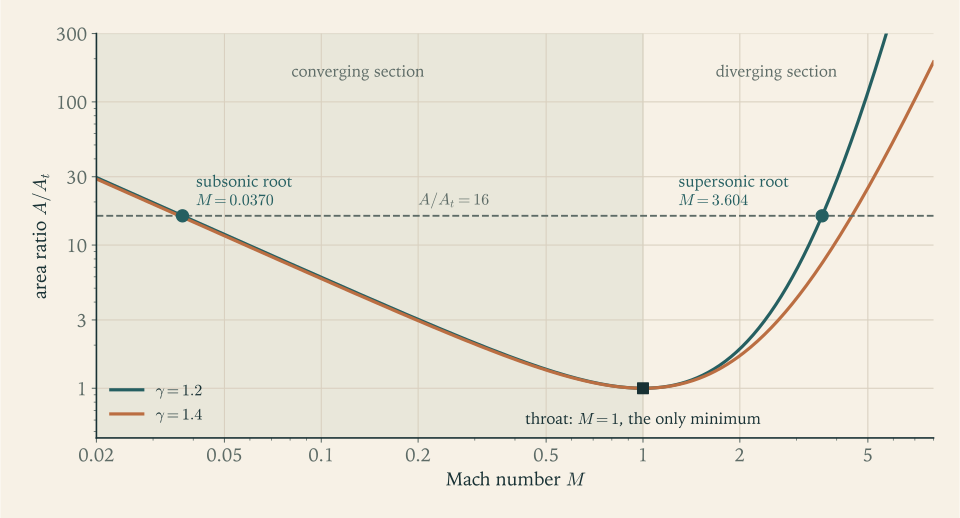
The function \(\mathcal A\) equals \(1\) at \(M=1\) , decreases on \((0,1)\) , increases on \((1,\infty)\) , and tends to infinity at both ends. Every area ratio greater than \(1\) therefore corresponds to exactly two Mach numbers, one subsonic and one supersonic.
The monotonicity follows from the logarithmic derivative, which a short calculation gives as
negative below \(M=1\) and positive above. Figure 5.1 shows the function. The two roots are both physical. Upstream of the throat, where the passage converges, the gas is on the subsonic branch; downstream, in the bell, it is on the supersonic branch. A nozzle designer chooses areas, so the practical question runs the other way: given \(A/A_t\) , what is \(M\) ? The relation cannot be solved for \(M\) in closed form. It has to be inverted numerically.
Two methods from the mathematics library do the job, and their hypotheses are easy to check here.
Bisection. For a continuous function that takes values of opposite sign at the ends of an interval, repeatedly halving the interval and keeping the half with the sign change converges to a root, and the error after \(j\)
steps is at most the original width divided by \(2^j\)
; this is the bracketing result of Numerical Analysis (math.numerical-analysis.root-bracketing). The function \(\mathcal A(M)-A/A_t\)
is continuous for \(M>0\)
. On the supersonic side it is negative at \(M=1\)
and positive for large \(M\)
, and since \(\mathcal A\)
is increasing there the root is unique. On the subsonic side the same holds on an interval from a small positive number to \(1\)
.
Newton’s method. For a twice continuously differentiable function with a simple root, the iteration \(M_{j+1}=M_j-[\mathcal A(M_j)-A/A_t]/\mathcal A'(M_j)\)
converges quadratically when started close enough to the root (math.numerical-analysis.newton-fixed-point). The derivative is available from the formula above. The qualification matters: \(\mathcal A'(1)=0\)
, so a start near \(M=1\)
sends the first step far away, and a start on the wrong side of \(M=1\)
converges, if at all, to the wrong branch.
Example 5.3: Exit conditions of a nozzle with area ratio 16
Problem. A nozzle on the model chamber has \(A_e/A_t=16\) . Find the exit Mach number, pressure, temperature, and velocity.
Bisection on the supersonic branch. \(\mathcal A(1)=1\) and \(\mathcal A(10)=31\,623\) , so \([1,10]\) brackets the root of \(\mathcal A(M)=16\) .
| Step | Interval | Midpoint | \(\mathcal A\) at midpoint | Keep |
|---|---|---|---|---|
| 1 | \([1,\ 10]\) | \(5.5\) | \(228.1\) | lower half |
| 2 | \([1,\ 5.5]\) | \(3.25\) | \(9.602\) | upper half |
| 3 | \([3.25,\ 5.5]\) | \(4.375\) | \(48.54\) | lower half |
| 4 | \([3.25,\ 4.375]\) | \(3.8125\) | \(21.63\) | lower half |
| 5 | \([3.25,\ 3.8125]\) | \(3.53125\) | \(14.39\) | upper half |
| 6 | \([3.53125,\ 3.8125]\) | \(3.671875\) | \(17.64\) | lower half |
Six steps have confined the root to an interval of width \(0.14\) . Reaching a width of \(10^{-6}\) from an initial width of \(9\) takes \(24\) steps, since \(9/2^{24}\) is about \(5\times10^{-7}\) .
Newton’s method from \(M_0=3\) .
| Iterate | \(M_j\) | \(\mathcal A(M_j)\) |
|---|---|---|
| 0 | \(3.000000\) | \(6.7354\) |
| 1 | \(3.980048\) | \(27.5507\) |
| 2 | \(3.689503\) | \(18.0987\) |
| 3 | \(3.609408\) | \(16.1174\) |
| 4 | \(3.604374\) | \(16.0004\) |
| 5 | \(3.604355\) | \(16.0000\) |
The error falls from \(0.6\) to \(0.38\) , \(0.085\) , \(0.005\) , and then \(0.00002\) : once close, each step roughly squares it. Five steps do what bisection needs two dozen for. Started from \(M_0=1.2\) , however, the same iteration jumps to \(M_1=46\) , because the derivative there is nearly zero, and takes many steps to come back. A safe recipe is a few steps of bisection to get close, then Newton.
The subsonic root. Bisection on \([0.001,\ 1]\) gives \(M=0.0370\) . In the converging section, where the area is sixteen times the throat area, the gas is moving at only four percent of the speed of sound.
Exit state. With \(M_e=3.604\) , \(1+\tfrac{\gamma-1}{2}M_e^2=1+(0.1)(12.991)=2.2991\) :
Check. Theorem 4.5 with the pressure ratio \(1/0.00677\) gives the same \(2971\ \mathrm{m/s}\) , as it must, since both come from the energy equation and the isentropic relation. The exit pressure ratio is a small number raised from a sixth power, so it is sensitive to rounding: using \(M_e=3.60\) instead of \(3.604\) changes \(p_e\) by \(0.8\) percent.
Sensitivity to \(\gamma\) . The same area ratio with \(\gamma=1.3\) gives \(M_e=4.003\) and \(p_e=49.5\ \mathrm{kPa}\) , a quarter lower. The exit pressure of a given nozzle depends noticeably on the gas, which is one reason the single-\(\gamma\) model should not be trusted to the last percent.
The opposite question, what area ratio expands the gas to a chosen pressure, needs no iteration. The pressure fixes the Mach number through the formula of Section 5.1, and the Mach number fixes the area.
Example 5.4: The area ratio for a chosen exit pressure
Matched at sea level. For the model chamber to exhaust at \(p_e=101.325\ \mathrm{kPa}\) , the pressure ratio is \(p_c/p_e=98.69\) . Solving \(1+0.1M^2=(98.69)^{1/6}=2.1497\) gives
A vacuum engine. The Merlin Vacuum engine has a nozzle of area ratio \(165\) (Falcon User’s Guide; see sources). For the model gas, inverting Theorem 5.4 numerically gives \(M_e=5.257\) and
so \(3.5\ \mathrm{kPa}\) from a \(10\ \mathrm{MPa}\) chamber.
Reading the numbers. Going from area ratio \(11.75\) to \(165\) , fourteen times the exit area, raises the Mach number from \(3.4\) to \(5.3\) and lowers the exit pressure twenty-nine-fold. Section 4.5 showed how little velocity that buys. The next section puts the whole trade into one coefficient.
5.5 The thrust coefficient, and the best exit area
Divide the thrust equation of Theorem 3.3 by \(p_cA_t\) . The momentum term becomes \(\dot mv_e/(p_cA_t)=v_e/c^\ast=\Gamma v_e/\sqrt{RT_c}\) , and Theorem 4.5 supplies \(v_e\) .
Theorem 5.5 (ideal thrust coefficient). For a choked nozzle flowing full, with exit pressure \(p_e\) determined by the area ratio through Theorem 5.4,
The chamber temperature and the molar mass have cancelled. The thrust coefficient depends on \(\gamma\) , on the area ratio, and on the ratio \(p_a/p_c\) , and on nothing else. This completes the separation announced in Section 3.7: \(c=c^\ast C_F\) , with \(c^\ast=\sqrt{RT_c}/\Gamma\) a property of the hot gas and \(C_F\) a property of the nozzle and its surroundings.
Its limits are worth knowing. With no diverging section at all, \(A_e=A_t\) , the exit is the sonic throat and the thrust in vacuum is \(\dot mu_t+p_tA_t\) . Since \(\dot mu_t=\rho_tu_t^2A_t=\gamma p_tA_t\) , this is \((\gamma+1)p_tA_t\) , so \(C_F=(\gamma+1)(2/(\gamma+1))^{\gamma/(\gamma-1)}=1.242\) for \(\gamma=1.2\) . With an infinitely large nozzle in vacuum, \(p_e\to0\) and \(C_F\to\Gamma\sqrt{2\gamma/(\gamma-1)}=2.247\) . Every real nozzle lies between: the bell can add at most \(81\) percent to what the chamber and throat provide.
Which area ratio is best? Section 3.5 argued, by adding a ring of wall, that thrust is greatest when \(p_e=p_a\) . The momentum equation of Section 5.2 turns that argument into a calculation. Consider the quantity \(\dot mu+(p-p_a)A\) evaluated at a station of area \(A\) : it is the thrust the engine would have if the nozzle were cut off there. Its change between neighbouring stations is
because \(\dot m\,\mathrm du=\rho uA\,\mathrm du=-A\,\mathrm dp\) .
Theorem 5.6 (optimum expansion). For a full-flowing nozzle with fixed chamber conditions and throat,
Since \(p_e\) decreases as \(A_e\) increases, the thrust has a single maximum, at the exit area for which \(p_e=p_a\) .
The integral form is Proposition 3.4 made explicit for the bell. The element \(\mathrm dA\) is the area of a ring of wall projected onto a plane across the axis, and \((p-p_a)\,\mathrm dA\) is the forward force on that ring. Each ring adds thrust as long as the gas pressure on it exceeds the ambient pressure, and subtracts thrust afterward.
Example 5.5: Thrust coefficient and specific impulse for four nozzles
Setup. The model chamber, \(p_c=10\ \mathrm{MPa}\) and \(c^\ast=1759\ \mathrm{m/s}\) , with nozzles of area ratio \(10\) , \(16\) , \(25\) , and \(165\) . The ideal specific impulse is \(c^\ast C_F/g_0\) . At sea level \(p_a/p_c=0.01013\) .
One case in full. For \(A_e/A_t=16\) , Example 5.3 gave \(p_e/p_c=0.00677\) , so the bracket is \(1-(0.00677)^{1/6}=0.5651\) and
Then \(I_{sp,\mathrm{vac}}=(1759)(1.797)/9.80665=322.3\ \mathrm s\) and \(I_{sp,\mathrm{SL}}=293.3\ \mathrm s\) .
All four.
| Area ratio | Exit pressure | \(C_F\) in vacuum | \(C_F\) at sea level | Ideal \(I_{sp}\) in vacuum | Ideal \(I_{sp}\) at sea level |
|---|---|---|---|---|---|
| \(10\) | \(125.4\ \mathrm{kPa}\) | \(1.742\) | \(1.641\) | \(312.5\ \mathrm s\) | \(294.3\ \mathrm s\) |
| \(16\) | \(67.7\ \mathrm{kPa}\) | \(1.797\) | \(1.635\) | \(322.3\ \mathrm s\) | \(293.3\ \mathrm s\) |
| \(25\) | \(38.0\ \mathrm{kPa}\) | \(1.842\) | \(1.589\) | \(330.5\ \mathrm s\) | \(285.0\ \mathrm s\) |
| \(165\) | \(3.5\ \mathrm{kPa}\) | \(1.983\) | \(0.311\) | \(355.7\ \mathrm s\) | not attainable |
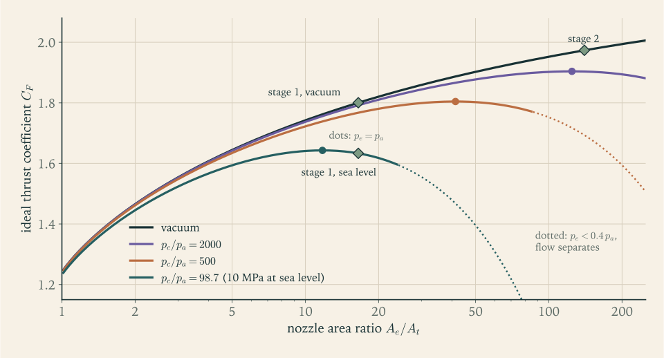
Reading the table. In vacuum, more area always helps, with diminishing returns: the step from \(10\) to \(25\) gains \(18\ \mathrm s\) , and the far larger step from \(25\) to \(165\) gains \(25\ \mathrm s\) . At sea level the best of these is the smallest, because it is nearest the matched ratio of \(11.75\) found in Example 5.4, where the sea-level coefficient peaks at \(1.643\) . The peak is flat: area ratios of \(10\) and \(16\) are both within half a percent of it. The last row is discussed in Section 5.6.
A first stage wants neither extreme. Example 3.4 showed that a first stage spends most of its burn near vacuum. Between area ratios \(16\) and \(25\) the nozzle gives up \(8\ \mathrm s\) on the pad to gain \(8\ \mathrm s\) in vacuum, a good trade if nothing else intervened. Two other limits will intervene.
Figure 5.2 shows the coefficient as a function of area ratio for several ambient pressures.
Example 5.6: Which part of the engine makes the thrust
Question. For a nozzle of area ratio \(16.5\) on the model chamber, how much of the thrust comes from the chamber and convergent section, and how much from the bell?
Up to the throat. By the limit computed above, an engine cut off at its throat has \(C_F=1.242\) in vacuum. This is the net effect of the pressure on the injector face, pushing forward, and on the convergent wall, pushing back.
The bell. For area ratio \(16.5\) Theorem 5.5 gives \(C_{F,\mathrm{vac}}=1.800\) . By Theorem 5.6 the difference is the integral of pressure over the bell wall:
which is \(31\) percent of the vacuum thrust.
At sea level. The atmosphere subtracts \(p_a/p_c=0.0101\) per unit of area ratio: \(0.010\) from the throat part and \((0.0101)(15.5)=0.157\) from the bell. The bell’s contribution falls to \(0.402\) and the total to \(1.633\) .
What it means. Two thirds of the thrust is pressure on the front of the chamber, less the pressure on the convergent wall. The remaining third is gas pressure on the inside of the bell, a pressure that falls from \(5.6\ \mathrm{MPa}\) at the throat to \(65\ \mathrm{kPa}\) at the lip but acts on fifteen times the throat’s area. The arrows on the right of Figure 3.1 were drawn from this calculation. The bell is not a passive skirt hung behind the engine. It pushes the engine forward, bearing on the throat from behind, and its share of the thrust reaches the vehicle through the chamber walls.
5.6 Too much nozzle
The last row of the table in Example 5.5 gave a sea-level thrust coefficient of \(0.311\) for the area ratio of \(165\) : less than a fifth of what the same chamber delivers through a small nozzle. The formula is saying that the atmosphere’s push on that enormous bell, at \(101\ \mathrm{kPa}\) outside against a few kilopascals inside, cancels most of the thrust. An engine that weak could not lift its own stage.
The real outcome is different, and in one respect worse. The formula assumed that the flow fills the nozzle to the lip. Along the wall of any nozzle there is a thin layer of slow gas held back by friction. When the pressure in the main stream is far below ambient, the outside air pushes into that slow layer from the exit and peels the stream off the wall. This is flow separation. Downstream of the separation point the jet runs through the middle of the bell without touching it, and the space between is filled with air at close to ambient pressure.
Where does this happen? One set of lecture notes states that a nozzle is likely to stay full while the ambient pressure is less than \(2\) to \(2.5\) times the exit pressure, and that beyond that the flow separates at the station where the wall pressure is about \(1/2\) to \(1/2.5\) of ambient (MIT 16.50 notes, Lecture 7; see sources). Another summary puts the threshold at an exit pressure of “approximately 40%” of ambient (Wikipedia, “Rocket engine nozzle”; see sources). This is an empirical rule with a spread, not a theorem.
Proposition 5.7 (separation limit, empirical). A nozzle flows full when \(p_e\ge0.4\,p_a\) to \(0.5\,p_a\) , roughly. Below that the stream separates from the wall near the station where its pressure has fallen to about \(0.4\,p_a\) , and the thrust is approximately that of a nozzle cut off at that station.
Example 5.7: A vacuum nozzle on the launch pad
Where it separates. At sea level the separation pressure is about \(0.4\times101.325=40.5\ \mathrm{kPa}\) , a pressure ratio \(p_c/p=246.7\) for the model chamber. As in Example 5.4, \(1+0.1M^2=(246.7)^{1/6}=2.504\) , so \(M=3.879\) and
The flow leaves the wall where the bell has reached about a seventh of its final area.
Thrust. Treating the engine as a nozzle of area ratio \(23.8\) , Theorem 5.5 gives \(C_F=1.597\) at sea level, an ideal \(286\ \mathrm s\) . Separation has rescued most of the thrust that the attached-flow formula said was lost.
Why it is still unacceptable. The separation line is not steady and not symmetric. It wanders, and wherever it sits lower on one side than the other, ambient pressure acts on unequal areas and pushes the bell sideways. A thin bell sized for vacuum is not built to take such loads. This is why an upper-stage engine is not fired at full expansion on the ground, and why the engine families of Chapters 1 and 3 have a short-nozzle version for the first stage and a long-nozzle version for the second.
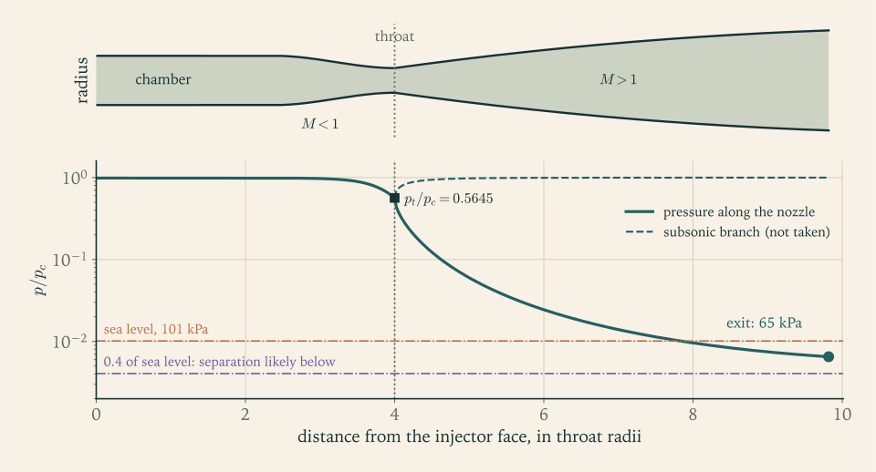
Figure 5.3 puts the pieces of the chapter on one picture: the forced shape, the pressure falling along it, and the ambient levels it must be compared with.
5.7 What real nozzles lose
Three effects separate a real nozzle from Theorem 5.5.
Divergence. The gas near the wall of a conical bell leaves along the wall, at an angle to the axis, and only the axial component of its momentum is thrust. Model the exit flow of a cone of half-angle \(\alpha_n\) as radial from the cone’s apex, with uniform speed over a spherical cap. A ring of the cap at angle \(\alpha'\) from the axis has area proportional to \(\sin\alpha'\) and contributes axial momentum in proportion to \(\cos\alpha'\) , so the momentum thrust is reduced by the factor
For a half-angle of \(15^\circ\) this is \(0.983\) . The figure agrees with the statement that a cone of about \(15^\circ\) half-angle “is about 98% efficient”, and that contoured bells, which turn the flow back toward the axis, do about one percent better while being shorter (Wikipedia, “Rocket engine nozzle”; see sources).
Friction and heat loss. The slow layer at the wall has lost momentum to friction and energy to the wall. Friction raises the entropy of the gas, and Section 4.7 showed that this lowers the exit velocity. Heat given up to the wall is a different loss. It lowers the entropy of the gas that loses it, and it cuts the exit velocity by another route: it removes part of the stagnation enthalpy that the expansion had to spend.
Chemistry. The single-\(\gamma\) model ignores recombination in the nozzle (Section 4.6). This error has the opposite sign: real gas gets energy back as it cools, so an equilibrium calculation predicts more than the model of this course. For expansion to area ratio \(40\) in vacuum the tabulated ideal exhaust velocity is \(3510\ \mathrm{m/s}\) (Wikipedia, “Liquid rocket propellant”; see sources); Theorem 5.5 with the model gas gives \(C_F=1.884\) and \(3314\ \mathrm{m/s}\) , which is \(5.6\) percent less.
So there are two gaps, and they should not be confused. The model of this course sits about \(5\) percent below the best theoretical calculation, because of its simplified gas. Real engines sit a few percent below the best theoretical calculation too, because of divergence, friction, incomplete combustion, and propellant spent on driving pumps (Chapter 6). The two shortfalls are of similar size, so delivered performance lands near the simple model’s prediction.
The factorization \(c=c^\ast C_F\) lets the comparison be pushed one step further for the two engines reduced in Chapter 3, but only as far as the data allow. What the published figures fix well is the product, thrust over mass flow. The RD-180’s \(338\ \mathrm s\) is within half a percent of the model’s ideal \(336.8\ \mathrm s\) for its area ratio of \(36.87\) , and the F-1’s \(304\ \mathrm s\) is \(94.3\) percent of the model’s \(322.3\ \mathrm s\) for area ratio \(16\) . The split into a chamber factor and a nozzle factor is less certain, because it passes through an exit area found from the difference of two thrusts quoted to the nearest \(10\ \mathrm{kN}\) . For the RD-180 that difference is \(320\ \mathrm{kN}\) , so \(c^\ast\) and \(C_F\) are each uncertain by about \(3\) percent, in opposite directions. The inferred \(c^\ast\) of \(1830\ \mathrm{m/s}\) is \(4.0\) percent above the model’s and the inferred vacuum \(C_F\) of \(1.815\) is \(3.3\) percent below the model’s ideal \(1.877\) . That pattern, a chamber better than the model gas and a nozzle short of the ideal one, is what the two gaps just described would produce, but differences of \(3\) to \(4\) percent are at the edge of what these data resolve, and the text claims no more than that they are consistent. For the F-1 the thrust difference is \(1000\ \mathrm{kN}\) and the uncertainty about \(1\) percent. Its \(c^\ast\) , \(4.8\) percent below the model, is therefore a real shortfall, and its thrust coefficients agree with the ideal for area ratio \(16\) to within that uncertainty. For the Merlin Vacuum, the quoted \(348\ \mathrm s\) is \(97.8\) percent of the model’s ideal \(355.7\ \mathrm s\) at area ratio \(165\) (secondary compilation for all three engines; see sources).
The practical rule for this course: take the ideal specific impulse from Theorem 5.5 with the model gas, and expect a real kerosene engine to deliver between about \(94\) and \(100\) percent of it. The reference launcher assumes \(97.5\) percent.
5.8 Nozzles for the reference launcher
First stage. Three quantities are already fixed: the mass flow \(811.1\ \mathrm{kg/s}\) and exit area \(2.355\ \mathrm{m^2}\) from Chapter 3, and now the throat area \(0.1427\ \mathrm{m^2}\) at \(p_c=10\ \mathrm{MPa}\) . Their ratio is the area ratio the earlier assumptions imply:
Example 5.8: Checking and choosing the first-stage area ratio
Exit state at area ratio \(16.5\) . Inverting Theorem 5.4: \(M_e=3.626\) , \(p_e/p_c=0.00650\) , so \(p_e=65.0\ \mathrm{kPa}\) , with \(T_e=1555\ \mathrm K\) and \(v_e=2978\ \mathrm{m/s}\) . Chapter 4’s round figure of \(60\ \mathrm{kPa}\) was close; the geometry gives \(65\ \mathrm{kPa}\) .
Ideal performance. \(C_{F,\mathrm{vac}}=1.800\) and \(C_{F,\mathrm{SL}}=1.633\) , so the ideal specific impulses are \(322.9\ \mathrm s\) and \(293.0\ \mathrm s\) . The values adopted in Chapter 3 are \(315/322.9=0.975\) and \(285/293.0=0.973\) of these. The reference engine is asked for \(97.5\) percent of ideal, inside the range found for real engines in Section 5.7.
Separation margin on the pad. \(p_e/p_{\mathrm{SL}}=65.0/101.325=0.64\) , comfortably above the limit of \(0.4\) to \(0.5\) . If the engines are throttled to \(60\) percent on the pad, the chamber pressure and with it every pressure in the nozzle falls to \(60\) percent, and \(p_e/p_{\mathrm{SL}}=0.385\) : at the limit. Deep throttling is for high altitude.
Would a larger nozzle be better? Keep the throat, the flow, and the \(97.5\) percent, change the area ratio, and repeat the vertical-climb calculation of Example 3.4. The effective values below are for comparing nozzles on that one estimate; the flight average on the trajectory the vehicle actually flies is computed in Chapter 7.
| Area ratio | \(p_e/p_{\mathrm{SL}}\) | \(I_{sp}\) at sea level | \(I_{sp}\) in vacuum | Effective \(I_{sp}\) over the vertical climb | Liftoff thrust-to-weight |
|---|---|---|---|---|---|
| \(12\) | \(0.97\) | \(286.9\ \mathrm s\) | \(308.7\ \mathrm s\) | \(304.7\ \mathrm s\) | \(1.309\) |
| \(16.5\) | \(0.64\) | \(285.0\ \mathrm s\) | \(315.0\ \mathrm s\) | \(309.4\ \mathrm s\) | \(1.300\) |
| \(20\) | \(0.50\) | \(282.2\ \mathrm s\) | \(318.5\ \mathrm s\) | \(311.6\ \mathrm s\) | \(1.287\) |
| \(25\) | \(0.38\) | \(276.9\ \mathrm s\) | \(322.3\ \mathrm s\) | \(313.6\ \mathrm s\) | \(1.263\) |
Judgment. A nozzle matched to sea level, near area ratio \(12\) , would be a poor choice: it gains \(2\ \mathrm s\) on the pad and loses \(5\ \mathrm s\) over the flight. Going up from \(16.5\) to \(20\) gains \(2.2\ \mathrm s\) of effective specific impulse, worth about \(75\ \mathrm{kg}\) of payload by the exchange ratio of Example 2.6, at the cost of one percent of liftoff thrust and all of the separation margin. Going to \(25\) crosses the separation limit on the pad. The design keeps \(16.5\) : it captures most of the available gain and leaves room to throttle. The F-1, a first-stage engine built for the same job, is listed with an area ratio of \(16\) (secondary compilation; see sources).
Second stage. The upper engine never meets the atmosphere, so separation does not limit it and the trade is against size and mass. Chapter 2 assumed \(345\ \mathrm s\) . At \(97.5\) percent of ideal that requires an ideal \(353.8\ \mathrm s\) , which Theorem 5.5 delivers at an area ratio close to \(140\) . Adopt \(A_e/A_t=140\) : then \(M_e=5.136\) , \(p_e=4.3\ \mathrm{kPa}\) , \(C_{F,\mathrm{vac}}=1.973\) , the ideal specific impulse is \(354.0\ \mathrm s\) , and \(97.5\) percent of it is \(345.1\ \mathrm s\) . With the flow \(\dot m_2=83.60\ \mathrm{kg/s}\) of Revision A at \(p_c=10\ \mathrm{MPa}\) , the throat area is \(0.01470\ \mathrm{m^2}\) , a throat \(0.137\ \mathrm m\) across, and the exit area is \(2.059\ \mathrm{m^2}\) , a bell \(1.62\ \mathrm m\) across at the lip.
The reference launcher’s propulsion after this chapter, for the Revision A masses and flows:
| Quantity | Stage 1 (three engines together) | Stage 2 (one engine) |
|---|---|---|
| Chamber pressure \(p_c\) | \(10\ \mathrm{MPa}\) | \(10\ \mathrm{MPa}\) |
| Characteristic velocity \(c^\ast\) (ideal) | \(1759\ \mathrm{m/s}\) | \(1759\ \mathrm{m/s}\) |
| Mass flow | \(811.1\ \mathrm{kg/s}\) | \(83.60\ \mathrm{kg/s}\) |
| Throat area \(A_t\) | \(0.1427\ \mathrm{m^2}\) | \(0.01470\ \mathrm{m^2}\) |
| Area ratio \(A_e/A_t\) | \(16.5\) | \(140\) |
| Exit area \(A_e\) | \(2.355\ \mathrm{m^2}\) | \(2.059\ \mathrm{m^2}\) |
| Exit pressure \(p_e\) | \(65.0\ \mathrm{kPa}\) | \(4.3\ \mathrm{kPa}\) |
| Ideal \(C_F\) , sea level and vacuum | \(1.633\) and \(1.800\) | vacuum only, \(1.973\) |
| Ideal \(I_{sp}\) , sea level and vacuum | \(293.0\) and \(322.9\ \mathrm s\) | vacuum only, \(354.0\ \mathrm s\) |
| Delivered \(I_{sp}\) assumed | \(285\) and \(315\ \mathrm s\) | \(345\ \mathrm s\) |
| \(p_e/p_{\mathrm{SL}}\) on the pad | \(0.64\) | not fired at sea level |
No number in the earlier chapters has moved. What has changed is their standing: the specific impulses that Chapter 2 assumed and Chapter 3 refined are now the output of a stated chamber and two stated nozzles, with a stated efficiency.
The chamber itself is still a set of chosen numbers. Why \(10\ \mathrm{MPa}\) and not \(30\) ? Why kerosene? What does it take to force eight hundred kilograms a second into a chamber at a hundred atmospheres, and what do the tanks, pumps, and engines weigh? Those questions decide the last unexamined inputs of Chapter 2, the structural coefficients, and they are the subject of Chapter 6.
Exercises
-
Define the speed of sound and the Mach number, and state the area-velocity relation. Then explain, using the sign of \(M^2-1\) on each side, why a station where a steadily accelerating flow passes through \(M=1\) must be a minimum of the area and cannot be a maximum.
-
The atmosphere model of Section 3.4 gives a temperature of \(216.6\ \mathrm K\) between \(11\) and \(25\ \mathrm{km}\) . (a) Find the speed of sound in air there and at \(288\ \mathrm K\) . (b) A vehicle moves at \(600\ \mathrm{m/s}\) at \(15\ \mathrm{km}\) ; find its Mach number. (c) Explain why the same vehicle speed corresponds to a higher Mach number at altitude than at the surface.
Answer
(a) With \(R=287.0\ \mathrm{J/(kg\cdot K)}\) and \(\gamma=1.4\) : \(c_s=\sqrt{(1.4)(287.0)(216.6)}=295.0\ \mathrm{m/s}\) at altitude and \(340.2\ \mathrm{m/s}\) at \(288\ \mathrm K\) . (b) \(M=600/295.0=2.03\) . (c) The speed of sound depends only on temperature for a given gas, and the air at \(15\ \mathrm{km}\) is about \(70\ \mathrm K\) colder, so the same speed is a larger multiple of it.
-
Suppose the compression in a sound wave took place at constant temperature instead of constant entropy. (a) Show that the wave speed would be \(\sqrt{RT}\) . (b) Evaluate both formulas for air at \(288\ \mathrm K\) and give their ratio. (c) Say which physical assumption in the derivation of Section 5.1 decides between them, and why the isentropic one is appropriate.
Solution
(a) The weak-wave argument of Section 5.1 gave \(\mathrm dp=c_s^2\,\mathrm d\rho\) from mass and momentum alone, before any statement about heat. If the temperature stayed fixed during the compression, the ideal-gas law \(p=\rho RT\) would give \(\mathrm dp=RT\,\mathrm d\rho\) , and hence a wave speed of \(\sqrt{RT}\) .
(b) For air at \(288\ \mathrm K\) with \(R=287.0\ \mathrm{J/(kg\cdot K)}\) :
\[ \sqrt{RT}=\sqrt{(287.0)(288)}=287.5\ \mathrm{m/s},\qquad \sqrt{\gamma RT}=\sqrt{(1.4)(287.0)(288)}=340.2\ \mathrm{m/s}. \]Their ratio is \(\sqrt\gamma=1.183\) .
(c) The deciding assumption is whether heat has time to flow between the compressed and uncompressed parts of the gas while the wave passes. For the temperature to stay constant, the heat of compression would have to leak away within a fraction of the wave’s period, over a distance of half a wavelength. Gases conduct heat far too slowly for that at any ordinary frequency, so each parcel is compressed adiabatically, and because the disturbance is weak there is no friction either. Adiabatic and reversible means constant entropy, which gives \(\gamma RT\) . The observed speed of sound in air, about \(340\ \mathrm{m/s}\) , agrees with the isentropic formula and not with the isothermal one.
-
Starting from the energy equation and the definition of the Mach number, derive \(T_c/T=1+\tfrac{\gamma-1}{2}M^2\) . Then show that as \(M\to\infty\) the flow speed tends to \(\sqrt{2c_pT_c}\) while the sound speed tends to zero, and explain how a flow can have a finite speed and an infinite Mach number.
Hint
Divide \(c_pT_c=c_pT+\tfrac12u^2\) by \(c_pT\) and use \(u^2=M^2\gamma RT\) with \(c_p=\gamma R/(\gamma-1)\) . For the limit, write \(u^2=2c_p(T_c-T)\) and note that \(M\to\infty\) forces \(T\to0\) . The Mach number grows without bound because its denominator, the local sound speed, goes to zero as the gas cools, not because its numerator does anything unusual.
-
Using the formula for \(\rho u\) in Section 5.3, show by logarithmic differentiation that the mass flow per unit area has a single maximum at \(M=1\) , and evaluate \(\rho u\) there for the model chamber gas at \(10\ \mathrm{MPa}\) .
Solution
Write \(\rho u=K\,M\,\bigl(1+\tfrac{\gamma-1}{2}M^2\bigr)^{-\frac{\gamma+1}{2(\gamma-1)}}\) with \(K=p_c\sqrt{\gamma/(RT_c)}\) constant. Taking the logarithm and differentiating with respect to \(M\) ,
\[ \frac{\mathrm d\ln(\rho u)}{\mathrm dM}=\frac1M-\frac{\gamma+1}{2(\gamma-1)}\cdot\frac{(\gamma-1)M}{1+\frac{\gamma-1}{2}M^2} =\frac{1+\frac{\gamma-1}{2}M^2-\frac{\gamma+1}{2}M^2}{M\left(1+\frac{\gamma-1}{2}M^2\right)}=\frac{1-M^2}{M\left(1+\frac{\gamma-1}{2}M^2\right)}. \]The denominator is positive for \(M>0\) , so the derivative is positive for \(M<1\) , zero at \(M=1\) , and negative for \(M>1\) . The mass flux therefore rises to a single maximum at \(M=1\) and falls afterward. This is the negative of the logarithmic derivative of \(\mathcal A\) in Theorem 5.4, as it must be, since \(\mathcal A\) is the ratio of the maximum flux to the local flux.
At \(M=1\) the flux is \(\Gamma p_c/\sqrt{RT_c}=p_c/c^\ast\) . For the model chamber,
\[ \rho_tu_t=\frac{10\times10^{6}\ \mathrm{Pa}}{1759\ \mathrm{m/s}}=5685\ \mathrm{kg/(m^2\cdot s)}. \]As a check, \(\rho_t=\rho_c(2/2.2)^{5}=(7.684)(0.6209)=4.771\ \mathrm{kg/m^3}\) and \(u_t=1192\ \mathrm{m/s}\) , whose product is the same.
-
The F-1 engine runs at \(p_c=7.0\ \mathrm{MPa}\) , and Exercise 3.4 inferred a throat area of \(0.6168\ \mathrm{m^2}\) from published figures (secondary compilation; see sources). (a) Use Theorem 5.3 with the model chamber gas to predict its mass flow. (b) Compare with the listed \(2578\ \mathrm{kg/s}\) . (c) State what the comparison implies about the real engine’s characteristic velocity, and give one physical reason.
Solution
(a) Theorem 5.3 gives \(\dot m=p_cA_t/c^\ast\) , with \(c^\ast=1759\ \mathrm{m/s}\) for the model gas:
\[ \dot m=\frac{(7.0\times10^{6}\ \mathrm{Pa})(0.6168\ \mathrm{m^2})}{1759\ \mathrm{m/s}}=2455\ \mathrm{kg/s}. \](b) The listed flow is \(2578\ \mathrm{kg/s}\) , which is \(5.0\) percent more than the model predicts.
(c) More flow through the same throat at the same chamber pressure means a lower characteristic velocity: \(c^\ast=p_cA_t/\dot m=1675\ \mathrm{m/s}\) , which is \(4.8\) percent below the model’s value. Since \(c^\ast=\sqrt{RT_c}/\Gamma\) , the real chamber gas has a lower \(T_c/\mathcal M\) than the model assumes. Physical reasons include incomplete combustion, a mixture richer in fuel than the one that maximizes \(c^\ast\) (this engine is listed with a mixture ratio of \(2.27\) ), and the fact that part of the listed flow drives the turbine and never passes through the main chamber at chamber conditions. The comparison is only as good as the inferred throat area, which Exercise 3.4 found from a difference of rounded thrusts.
-
An engine is tested at sea level and then in a vacuum chamber, at the same chamber pressure and temperature. (a) How does its mass flow change, and why? (b) How does its thrust change? (c) The engine is then throttled to \(60\) percent of its chamber pressure at fixed chamber temperature; find the new mass flow, exit pressure, and exit velocity as fractions of their previous values, and the new vacuum thrust.
Solution
(a) The mass flow does not change. The throat is sonic in both tests, the mass flow of a choked nozzle is \(\Gamma p_cA_t/\sqrt{RT_c}\) , and the ambient pressure does not appear in that expression. Physically, the flow downstream of the throat is supersonic, so no pressure disturbance from outside can travel upstream to the chamber.
(b) The thrust rises by \(p_aA_e\) , the sea-level pressure times the exit area, by Corollary 3.5.
(c) With \(T_c\) fixed, \(c^\ast\) is unchanged, so \(\dot m=p_cA_t/c^\ast\) falls to \(60\) percent. The area ratio fixes the exit Mach number and hence the ratio \(p_e/p_c\) , so the exit pressure also falls to \(60\) percent. The exit velocity depends on \(T_c\) , the gas, and \(p_e/p_c\) , none of which changed, so it stays the same. The vacuum thrust \(\dot mv_e+p_eA_e\) has both terms reduced to \(60\) percent, so it is \(60\) percent of its previous value, and the vacuum specific impulse is unchanged. At sea level the term \(-p_aA_e\) is not reduced, so sea-level thrust falls by more than \(40\) percent and sea-level specific impulse drops; and the lower exit pressure brings the nozzle closer to separation.
-
A colleague proposes to raise exhaust velocity by welding a short converging cone onto the exit of a rocket nozzle, “since narrowing a passage speeds up the flow, as in a garden hose.” Use Theorem 5.2 to say what the cone would do to the speed and pressure of the exhaust, identify the assumption about the fluid that the hose intuition relies on, and state the Mach number range in which the intuition is correct.
Answer
The exhaust is supersonic, so by Theorem 5.2 a decreasing area makes \(\mathrm du\) negative: the cone would slow the gas and raise its pressure, and in practice would produce shock waves, thin layers in which a supersonic flow is abruptly and irreversibly slowed and compressed, and with them a large loss. The hose intuition assumes constant density, which is the limit \(M\to0\) ; it is correct for \(M<1\) , where the factor \(M^2-1\) is negative.
-
A student estimates the mass flow of an engine as \(\rho_c\,c_{s,c}\,A_t\) , the chamber density times the chamber sound speed times the throat area. (a) Show that this exceeds the correct value by the factor \(\bigl((\gamma+1)/2\bigr)^{(\gamma+1)/(2(\gamma-1))}\) . (b) Evaluate the factor for \(\gamma=1.2\) . (c) Identify the two physical errors in the estimate.
Solution
(a) The correct mass flow is \(\rho_tu_tA_t\) , with throat density and throat speed. From Section 5.3, \(\rho_t=\rho_c\bigl(2/(\gamma+1)\bigr)^{1/(\gamma-1)}\) and \(u_t=\sqrt{\gamma RT_t}=c_{s,c}\bigl(2/(\gamma+1)\bigr)^{1/2}\) , where \(c_{s,c}=\sqrt{\gamma RT_c}\) . So
\[ \frac{\rho_c\,c_{s,c}\,A_t}{\rho_tu_tA_t}=\left(\frac{\gamma+1}{2}\right)^{\frac1{\gamma-1}+\frac12}=\left(\frac{\gamma+1}{2}\right)^{\frac{\gamma+1}{2(\gamma-1)}}. \](b) For \(\gamma=1.2\) the factor is \((1.1)^{5.5}=1.689\) . The estimate is \(69\) percent too high.
(c) First, the gas at the throat is not at chamber density: it has expanded to \(62\) percent of it on the way. Second, it is not at chamber temperature either, so the sound speed at the throat, which is the flow speed there, is lower than the chamber sound speed by the factor \(\sqrt{2/(\gamma+1)}=0.953\) . Both the density and the speed must be evaluated where the flow is sonic.
-
(Computation.) Write a program that inverts the area-Mach relation by bisection followed by Newton’s method. For \(\gamma=1.2\) find both roots for \(A/A_t=25\) and \(A/A_t=80\) , and for \(\gamma=1.3\) find the supersonic root for \(A/A_t=25\) . Report each root to five significant figures, the exit pressure ratio on the supersonic branch, and the number of Newton steps needed from a starting value of \(M=3\) to reach an error below \(10^{-8}\) .
Answer
For \(\gamma=1.2\) , \(A/A_t=25\) : subsonic \(M=0.023688\) , supersonic \(M=3.9128\) with \(p_e/p_c=3.804\times10^{-3}\) ; Newton from \(M=3\) needs \(6\) steps. For \(A/A_t=80\) : subsonic \(M=0.0074005\) , supersonic \(M=4.7294\) with \(p_e/p_c=8.698\times10^{-4}\) ; \(12\) steps, because the first step overshoots far to the right. For \(\gamma=1.3\) , \(A/A_t=25\) : supersonic \(M=4.4143\) with \(p_e/p_c=2.677\times10^{-3}\) ; \(7\) steps.
-
For the model chamber, find the area ratio that expands the gas to an exit pressure of \(30\ \mathrm{kPa}\) , and the exit Mach number, temperature, and velocity. Explain why this calculation needs no iteration while the reverse one does.
Solution
The exit pressure fixes the pressure ratio, \(p_c/p_e=10\,000/30=333.3\) , and the formula of Section 5.1 gives the Mach number directly:
\[ 1+0.1\,M_e^2=(333.3)^{1/6}=2.6332,\qquad M_e=\sqrt{16.332}=4.041 . \]Then Theorem 5.4 gives the area ratio by evaluation, \(\mathcal A(4.041)=30.09\) . The exit temperature is \(T_e=3600/2.6332=1367\ \mathrm K\) , the local sound speed is \(\sqrt{(1.2)(361.5)(1367)}=770.1\ \mathrm{m/s}\) , and \(v_e=(4.041)(770.1)=3112\ \mathrm{m/s}\) .
No iteration is needed because each step evaluates an explicit formula: pressure ratio to Mach number is an algebraic inversion, and Mach number to area is a substitution. The reverse problem starts from the area, and \(\mathcal A(M)\) cannot be solved for \(M\) algebraically; it also has two solutions, so a numerical method has to be told which branch to search.
-
A nozzle of area ratio \(16\) is run with two gases at the same chamber pressure of \(10\ \mathrm{MPa}\) : one with \(\gamma=1.2\) and one with \(\gamma=1.3\) . Example 5.3 gives the exit pressures as \(67.7\) and \(49.5\ \mathrm{kPa}\) . (a) Explain physically why the gas with larger \(\gamma\) leaves at lower pressure. (b) Which of the two is closer to separation at sea level? (c) What does this imply about predicting separation with a single-\(\gamma\) model?
Answer
(a) At a given area ratio the gas with larger \(\gamma\) reaches a higher Mach number, \(4.003\) against \(3.604\) (Figure 5.1), and so has expanded further: its temperature has fallen to \(0.294\) of the chamber value, against \(0.435\) . For a given drop in temperature its pressure actually falls less, since \(p/p_c=(T/T_c)^{\gamma/(\gamma-1)}\) has the exponent \(4.33\) instead of \(6\) , as Exercise 4.18 found. The larger temperature drop outweighs the smaller exponent: \((0.294)^{4.33}=0.0050\) against \((0.435)^{6}=0.0068\) . (b) The \(\gamma=1.3\) gas, with \(p_e/p_a=0.49\) at sea level against \(0.67\) . (c) Real exhaust has \(\gamma\) rising from about \(1.2\) toward \(1.3\) along the nozzle, so the true exit pressure lies between the two predictions, and a separation margin computed with \(\gamma=1.2\) is optimistic. Margins near the limit need a better gas model.
-
The tabulated ideal performance of kerosene and oxygen assumes a chamber pressure of \(68.05\) atmospheres, that is \(6.895\ \mathrm{MPa}\) , expanded to one atmosphere, and gives \(2941\ \mathrm{m/s}\) (Wikipedia, “Liquid rocket propellant”; see sources). (a) For the model gas, find the exit Mach number, the matched area ratio, and the thrust coefficient for the same expansion. (b) Find the model’s exhaust velocity and compare. (c) Give the main reason the model is lower.
Solution
(a) The expansion is matched: \(p_e=p_a\) with \(p_c/p_e=68.05\) . From Section 5.1,
\[ 1+0.1\,M_e^2=(68.05)^{1/6}=2.0206,\qquad M_e=\sqrt{10.206}=3.195,\qquad \frac{A_e}{A_t}=\mathcal A(3.195)=8.87 . \]With \(p_e=p_a\) the pressure term of Theorem 5.5 vanishes and
\[ C_F=\Gamma\sqrt{12\left[1-(68.05)^{-1/6}\right]}=(0.6485)\sqrt{(12)(0.5051)}=1.597 . \](b) The effective exhaust velocity is \(c=c^\ast C_F=(1759)(1.597)=2809\ \mathrm{m/s}\) . Because the nozzle is matched this is also the exit velocity, and Theorem 4.5 gives the same number. The tabulated value is \(2941\ \mathrm{m/s}\) , so the model is \(4.5\) percent low.
(c) Two things contribute. The model’s characteristic velocity, \(1759\ \mathrm{m/s}\) , is \(2.2\) percent below the tabulated \(1799\ \mathrm{m/s}\) , which reflects the chosen \(T_c\) and \(\mathcal M\) . The rest is in the nozzle: the tabulated calculation lets the gas composition shift as it cools, so dissociated fragments recombine and return energy to the flow, while the model’s gas has a fixed composition and a fixed \(\gamma\) . Recombination is the larger physical effect and the single-\(\gamma\) model cannot represent it.
-
Prove that for a full-flowing nozzle \(\mathrm dC_F/\mathrm d(A_e/A_t)=(p_e-p_a)/p_c\) , starting from the momentum equation \(\mathrm dp=-\rho u\,\mathrm du\) . Then use the result to explain why the maximum of \(C_F\) at a given ambient pressure is flat, and why that flatness is useful to a designer.
Solution
The thrust of a nozzle cut at area \(A\) is \(F=\dot mu+(p-p_a)A\) . Between neighbouring stations,
\[ \mathrm dF=\dot m\,\mathrm du+A\,\mathrm dp+(p-p_a)\,\mathrm dA . \]The mass flow is \(\dot m=\rho uA\) , so \(\dot m\,\mathrm du=A\,\rho u\,\mathrm du=-A\,\mathrm dp\) by the momentum equation. The first two terms cancel and \(\mathrm dF=(p-p_a)\,\mathrm dA\) . Dividing by \(p_cA_t\) , which is constant for a fixed chamber and throat,
\[ \frac{\mathrm dC_F}{\mathrm d(A_e/A_t)}=\frac{p_e-p_a}{p_c}. \]At the optimum the derivative is zero, and near it the derivative is the small quantity \((p_e-p_a)/p_c\) : both pressures are of order one percent of the chamber pressure or less. A change of a few units in area ratio therefore changes \(C_F\) by a few times \(10^{-3}\) at most. For the model chamber at sea level the coefficient is \(1.641\) at area ratio \(10\) , \(1.643\) at the optimum \(11.75\) , and \(1.635\) at \(16\) .
The flatness is useful because it lets the designer move away from the optimum for one ambient pressure at almost no cost there, and collect a first-order gain somewhere else. A first-stage nozzle is made larger than the sea-level optimum: it loses a fraction of a percent on the pad and gains several percent in vacuum, where the derivative \(p_e/p_c\) is always positive.
-
Two nozzles of area ratio \(16\) and \(25\) are fitted to identical chambers at \(10\ \mathrm{MPa}\) . Using the vacuum thrust coefficients of Example 5.5, (a) find the ambient pressure at which the two give equal thrust, (b) find the corresponding altitude from the atmosphere model of Section 3.4, and (c) say which nozzle is better below that altitude and which above.
Solution
(a) By Theorem 5.5 the thrust coefficient at ambient pressure \(p_a\) is the vacuum value minus \((p_a/p_c)(A_e/A_t)\) . The two nozzles give equal thrust when
\[ 1.8424-25\,\frac{p_a}{p_c}=1.7971-16\,\frac{p_a}{p_c}\qquad\Longrightarrow\qquad \frac{p_a}{p_c}=\frac{1.8424-1.7971}{9}=0.00503, \]so \(p_a=50.3\ \mathrm{kPa}\) . (Four-figure coefficients are needed here; with the three-figure values of Example 5.5 the difference \(0.045\) is known only to two figures.)
(b) In the lowest zone of the atmosphere model, \(p=101.29\,[(288.14-0.00649z)/288.08]^{5.256}\) in kilopascals. Solving for \(p=50.3\) gives \(z=5.54\ \mathrm{km}\) .
(c) Below \(5.5\ \mathrm{km}\) , where the ambient pressure exceeds \(50.3\ \mathrm{kPa}\) , the smaller nozzle gives more thrust; above it the larger one does. A first stage passes that altitude less than a third of the way through its burn (Example 3.4), which is why the larger nozzle wins on the flight as a whole, as long as it does not separate on the pad.
-
A first-stage engine with the model chamber at \(10\ \mathrm{MPa}\) is given a nozzle of area ratio \(25\) . (a) Find \(p_e/p_a\) at sea level and judge the risk of separation. (b) Find the altitude above which \(p_e/p_a\) exceeds \(0.5\) . (c) A designer argues that “it only separates for the first few seconds, so it does not matter.” Give one reason it might matter.
Answer
(a) \(p_e=38.0\ \mathrm{kPa}\) , so \(p_e/p_a=0.375\) at sea level: below the lower end of the empirical limit, so separation on the pad is likely. (b) \(p_e/p_a=0.5\) when \(p_a=76.1\ \mathrm{kPa}\) , at \(2.36\ \mathrm{km}\) . (c) Those first seconds include ignition and liftoff, when the vehicle is next to its launch structure, the engines are being checked before release, and side loads on the bells and through the gimbals act on a vehicle with no speed to stabilize it. Unsteady separation there can damage the nozzle or disturb the vehicle at the worst moment.
-
Derive the divergence factor \((1+\cos\alpha_n)/2\) for a conical nozzle by the argument of Section 5.7. Evaluate it for half-angles of \(10^\circ\) , \(15^\circ\) , and \(20^\circ\) , and for the \(15^\circ\) case find the vacuum thrust coefficient of the reference launcher’s first-stage nozzle when the factor is applied to the momentum term only. Why does the factor not multiply the pressure term?
Hint
Follow the spherical-cap argument: the area of a ring between \(\alpha'\) and \(\alpha'+\mathrm d\alpha'\) is proportional to \(\sin\alpha'\) , and the axial component of the momentum through it carries a factor \(\cos\alpha'\) . The values are \(0.9924\) , \(0.9830\) , and \(0.9698\) . For area ratio \(16.5\) the momentum term of \(C_{F,\mathrm{vac}}\) is \(1.6931\) and the pressure term \(0.1073\) , so with the \(15^\circ\) factor \(C_{F,\mathrm{vac}}=(0.9830)(1.6931)+0.1073=1.772\) , down \(1.6\) percent from \(1.800\) . Pressure is a scalar acting on the projected exit area, so it has no direction to lose.
-
For a nozzle of area ratio \(16.5\) and \(\gamma=1.2\) the subsonic root of the area-Mach relation at the exit is \(M=0.0359\) . (a) Find the exit pressure, as a fraction of chamber pressure, for flow that stays subsonic throughout with a sonic throat. (b) Explain why the nozzle is choked for any ambient pressure below this value. (c) Describe in words the pressure distribution along the nozzle in that subsonic case and in the supersonic case, and identify each with a curve in Figure 5.3.
Answer
(a) \(p/p_c=\bigl(1+(0.1)(0.0359)^2\bigr)^{-6}=0.99923\) . (b) If the ambient pressure equals this value, the flow accelerates to exactly \(M=1\) at the throat and decelerates again in the bell. Any lower ambient pressure cannot be matched by a fully subsonic flow, the throat stays sonic, and the mass flow is the choked value. So the nozzle is choked whenever the ambient pressure is below \(99.92\) percent of the chamber pressure. (c) Subsonic case: pressure falls to \(0.5645\,p_c\) at the throat and climbs back to almost \(p_c\) at the exit, the dashed curve of Figure 5.3. Supersonic case: pressure keeps falling through the bell to \(65\ \mathrm{kPa}\) , the solid curve. Ambient pressures between the two end values cannot be met by either smooth solution, and the real flow then contains shocks (the abrupt, irreversible compressions mentioned in the answer to Exercise 8, which this chapter does not treat) or separation.
-
This exercise uses Chapters 3 and 4. For the first-stage nozzle of area ratio \(16.5\) : (a) compute the ideal vacuum effective exhaust velocity as \(v_e+p_eA_e/\dot m\) using \(v_e=2978\ \mathrm{m/s}\) , \(p_e=65.0\ \mathrm{kPa}\) , and the exit area and mass flow of Example 3.2, and compare with \(c^\ast C_{F,\mathrm{vac}}\) ; (b) explain why the two agree only if the same mass flow is used in both; (c) find what fraction of the ideal vacuum thrust is pressure thrust.
Solution
(a) From the thrust equation, the ideal effective exhaust velocity in vacuum is
\[ c_{\mathrm{vac}}=v_e+\frac{p_eA_e}{\dot m}=2978+\frac{(65.0\times10^{3}\ \mathrm{Pa})(2.355\ \mathrm{m^2})}{811.1\ \mathrm{kg/s}}=2978+189=3167\ \mathrm{m/s}. \]From the factorization, \(c^\ast C_{F,\mathrm{vac}}=(1759)(1.800)=3167\ \mathrm{m/s}\) . The two agree.
(b) The first form uses the mass flow explicitly; the second uses it implicitly through \(c^\ast=p_cA_t/\dot m\) . They describe the same engine only if \(\dot m\) , \(p_c\) , and \(A_t\) satisfy that relation, which is how the throat area was computed in Example 5.2. Had the throat been sized with a different \(c^\ast\) , for instance a measured one, the pressure term \(p_eA_e/\dot m\) would have to be recomputed with the matching area ratio.
(c) The pressure thrust is \(189/3167=6.0\) percent of the ideal vacuum thrust; the other \(94\) percent is momentum thrust. This is consistent with Example 5.5, where the pressure term of \(C_{F,\mathrm{vac}}\) for a similar nozzle was \(0.108\) out of \(1.797\) .
-
For the reference launcher’s second-stage engine with area ratio \(140\) : (a) verify the exit Mach number \(5.136\) by evaluating \(\mathcal A\) there; (b) compute the exit pressure, temperature, and velocity; (c) compute the ideal vacuum thrust and the delivered thrust at \(97.5\) percent, and compare with the \(282.8\ \mathrm{kN}\) of Revision A; (d) the stage is \(3.0\ \mathrm m\) in diameter (a value Chapter 6 adopts): does the bell fit, and what would a nozzle of area ratio \(250\) require?
Solution
(a) With \(M=5.136\) : \(1+0.1M^2=3.6378\) , and
\[ \mathcal A(5.136)=\frac{1}{5.136}\left[\frac{3.6378}{1.1}\right]^{5.5}=\frac{(3.3071)^{5.5}}{5.136}=140.1 , \]which confirms the root to the accuracy of the rounded Mach number.
(b) \(p_e/p_c=(3.6378)^{-6}=4.32\times10^{-4}\) , so \(p_e=4.32\ \mathrm{kPa}\) ; \(T_e=3600/3.6378=990\ \mathrm K\) ; \(v_e=M_e\sqrt{\gamma RT_e}=(5.136)(655.2)=3365\ \mathrm{m/s}\) .
(c) The ideal vacuum thrust is \(C_Fp_cA_t=(1.9734)(10\times10^{6})(0.014705)=290.2\ \mathrm{kN}\) , and \(97.5\) percent of it is \(282.9\ \mathrm{kN}\) , matching the \(282.8\ \mathrm{kN}\) of Revision A. The agreement is by construction: the throat was sized for the Revision A flow with the ideal \(c^\ast\) , and the area ratio was chosen so that \(97.5\) percent of the ideal specific impulse is \(345\ \mathrm s\) .
(d) The exit diameter is \(1.62\ \mathrm m\) , which fits inside a \(3.0\ \mathrm m\) stage with room to swing the engine for steering. An area ratio of \(250\) would need an exit area of \(3.68\ \mathrm{m^2}\) , a bell \(2.16\ \mathrm m\) across and correspondingly longer, for an ideal specific impulse of \(359.8\ \mathrm s\) : a gain of \(5.9\ \mathrm s\) ideal, or about \(5.7\ \mathrm s\) delivered. It would still fit the diameter, but the bell’s area, and so roughly its mass, would be \(1.8\) times larger, and the interstage that encloses it would be longer. Whether \(5.7\ \mathrm s\) on the upper stage, worth about \(200\ \mathrm{kg}\) of payload by Example 2.6, repays that mass on the stage where mass is most expensive is a trade for Chapter 6.